
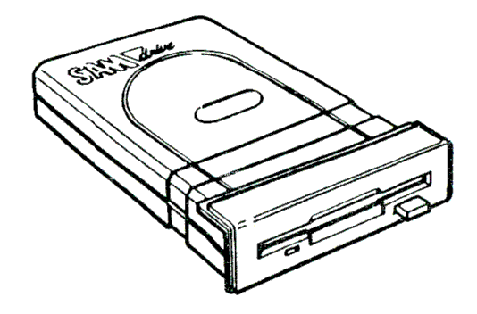
The Coupé could support two 3.5” Ultraslim Citizen Double Density (U0DC-xxx) drives each with their own WD-1770-02 disc controller board allowing both drives to operate independently.
Unformatted capacity 1Mbyte, when formatted with Samdos as double sided, 80 track per side, 10 sectors per track, to the IBM 3740 standard gives 800kB with 776kB usable after directory space and next sector data is subtracted.
Having the drive controller board within the slot-in drive unit meant that the floppy drive connectors could be used for other devices, most notably the ATOM IDE interface and (with Internal PCB modification) the Sam Internal Parallel Interface SIPI.
When the rights passed to West Coast Computers the Citizen drives were no longer available so modified PC drives were used instead, requiring a modified drive controller board and a large cut out of the front of a blanking plate. They also sold kits for additional drives made in this fashion called Project 94A.
With age brings maintainance requirements which are documented on the Drive Issues page.
Drive Connectors:
Connections to the two drives controllers are made via two 32-pin Euroconnectors, with rows A and B connected. Drive 1 (DS0) is on the left of the machine and drive 2 (DS1) on the right. A list of signals available at these sockets are shown below.
| PIN | SIGNAL | PIN | SIGNAL |
|---|---|---|---|
| 1A | 0 VOLTS | 1B | WR |
| 2A | 0 VOLTS | 2B | A0 |
| 3A | 0 VOLTS | 3B | A1 |
| 4A | 0 VOLTS | 4B | D0 |
| 5A | 0 VOLTS | 5B | D1 |
| 6A | 0 VOLTS | 6B | D2 |
| 7A | 0 VOLTS | 7B | D3 |
| 8A | 0 VOLTS | 8B | D4 |
| 9A | 0 VOLTS | 9B | D5 |
| 10A | 0 VOLTS | 10B | D6 |
| 11A | 5 VOLTS | 11B | D7 |
| 12A | 5 VOLTS | 12B | 8 MHz |
| 13A | 5 VOLTS | 13B | RST |
| 14A | 5 VOLTS | 14B | No connection |
| 15A | 5 VOLTS | 15B | A2 |
| 16A | 5 VOLTS | 16B | DS0 (wired to DS0 in left hand bay, DS1 in right hand bay) |
Citizen Drive Pin out:
The U0DC drives have no seperate power connector so use a custom 26-way connection to the drive controller board to pass 5V to the drive.
|
PIN |
SIGNAL |
PIN |
SIGNAL |
|---|---|---|---|
|
1 |
5 Volts |
14 |
Step |
|
2 |
Index |
15 |
Ground |
|
3 |
5 Volts |
16 |
Write Data |
|
4 |
Drive Select 0 |
17 |
Ground |
|
5 |
5 Volts |
18 |
Write Gate |
|
6 |
Not connected |
19 |
Ground |
|
7 |
Drive Select 1 |
20 |
Track 0 |
|
8 |
Ready |
21 |
Ground |
|
9 |
Not connected |
22 |
Write Protect |
|
10 |
Motor on |
23 |
Ground |
|
11 |
Not connected |
24 |
Read Data |
|
12 |
Direction |
25 |
Ground |
|
13 |
Ground |
26 |
Side 1 Select |
Drive Issues:
See the Drive Issues page.