Dallas Clock
Publisher
Description
The DALLAS clock was a clock unit that could be read by B-DOS (but not MasterDOS) in place of the SamBus Clock.
See the DALLAS Clock Page for more details, quote as follows:
I wanted to add a realtime clock to my SAM other then the hard to get realtime clock chip used in the sambus and discovered the realtime clock chip from dallas semiconductors which has two big advantages: All clock components inclusive a backup battery are in a single package so implementation is easy, and this clock can be found on PC motherboards which makes it easy to get.
The Dallas clock can operate in INTEL mode and MOTOROLA mode. In order to reduce the chip count I choose to use the MOTOROLA
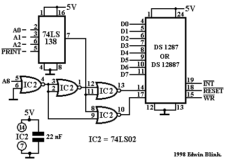
mode.My original design of the DALLAS clock was based on integration with the SAM's Comms interface (In which I already build my EDDAC interface). But to make it function as a stand alone interface a 74LS138 address decoder was added.
The extra 114 bytes on the chip (DS12887, 50 bytes on the DS1287) can also be used as non-volatile storage such as Defender for the 'All time high score' value.
Schematic
Attached.
Notes
I recommend fitting the clock chip in a 24 pin DIL socket. IC 2 and the ceramic capacitor can be fitted inside the DIL socket.
Software
The Dallas Clock is supported by B-DOS and also several utilities by Martijn Groen.
INTERFACE COMPONENTS
| 1 | DS 12887 (or DS 1287) |
| 1 | 74LS02 |
| 1 | 74LS138* |
| 1 | 22 nF ceramic capacitor |
| 1 | 22 uF/16V electrolytic capacitor * |
* Not required when clock is built inside Comms interface.
Additional Information by Richard Gadd
I built the interface using a GAL16V8 to handle the logic done by the 74LS02 and 74LS138 and mounted it internally. I originally followed the schematic, but I had a case where I noted the time format bit had been inverted. According to the data sheet:
RESET (Reset Input) – The RESET pin has no effect on the clock, calendar, or RAM. On power–up the RESET pin can be held low for a time in order to allow the power supply to stabilize. The amount of time that RESET is held low is dependent on the application. However, if RESET is used on power–up, the time RESET is low should exceed 200 ms to make sure that the internal timer that controls the DS12887 on power-up has timed out. When RESET is low and VCC is above 4.25 volts, the following occurs:
A. Periodic Interrupt Enable (PEI) bit is cleared to 0.
B. Alarm Interrupt Enable (AIE) bit is cleared to 0.
C. Update Ended Interrupt Flag (UF) bit is cleared to 0.
D. Interrupt Request Status Flag (IRQF) bit is cleared to 0.
E. Periodic Interrupt Flag (PF) bit is cleared to 0.
F. The device is not accessible until RESET is returned high.
G. Alarm Interrupt Flag (AF) bit is cleared to 0.
H. IRQ pin is in the high impedance state.
I. Square Wave Output Enable ( SQWE ) bit is cleared to 0.
J. Update Ended Interrupt Enable (UIE) is cleared to 0.
In a typical application RESET can be connected to VCC. This connection will allow the DS12887 to go in and out of power fail without affecting any of the control registers.
I manually tweaked the SQWE bit so it was set and then did a RESET and it appeared to clear the SQWE bit, but on a cold power-up the SQWE remained set. I surmised that on power-up the RESET was less than the 200ms required to allow the DALLAS chip start-up to timeout. Whether this attributed to the register getting corrupted I don't know but I have changed my implementation so the RESET signal fed into the DALLAS chip is always high. I also added the RESET signal into the DATA and STROBE logic (one of the advantages of using a GAL chip) to ensure there is no errant accesses to the DALLAS chip while the computer is in RESET.
Screenshots